
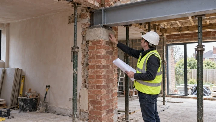
Building Regulations Part A: Structure Explained
Every structural change in a domestic building project must ensure that loads transfer safely to the ground. In England, Building Regulations Part A sets the statutory standard for structural safety across all building works. This standard governs everything from simple internal wall removals to substantial two-storey extensions. Approved Document A provides clear technical rules for loading, ground movement, and disproportionate collapse. Meeting these legal duties requires careful engineering design before construction begins. Every foundation, masonry pier, and supporting member must perform safely under permanent dead and variable imposed loads.
Homeowners and project managers often underestimate the technical justification that building control officers require on site. What specific calculations must an engineer supply to verify proposed alterations? How do steel beams, bearings, and foundations interact under building standards? Furthermore, what documentation ensures statutory sign-off without costly retrospective remedial work on site?
Key Takeaways
- Approved Document A requires every load-bearing element to transmit dead, imposed, and wind forces safely into competent subsoil without excessive deflection or structural instability.
- Independent structural calculations prepared by a qualified engineer provide the essential verification that building control approvers demand before approving alterations to existing load-bearing walls.
- Proper steel beam design must evaluate bending moments, shear capacity, web buckling, and allowable deflection limits alongside padstone bearing stresses on supporting masonry.
- Foundation depth and geometry depend entirely on localised soil strata, nearby tree influence, and existing drainage infrastructure rather than generic standard depth assumptions.
- Submitting full structural details through a Full Plans building control application significantly reduces commercial risk by securing formal statutory approval before site demolition commences.
Core Requirements of Approved Document A
Approved Document A sets out three functional requirements for structural safety: loading, ground movement, and disproportionate collapse. Every domestic alteration must demonstrate structural adequacy before work proceeds. Building control approvers review calculations against these benchmarks. This rigorous process prevents localised failures and excessive building movement.
The document provides prescriptive guidance for standard masonry dwellings. However, altered structures mandate detailed engineering design. Bespoke calculations become mandatory when openings exceed manufacturers’ lintel tables or when removing load-bearing partitions. The table below outlines primary statutory elements governed by Part A across typical residential projects.
| Statutory Element | Approved Document Requirement | Typical Residential Compliance |
|---|---|---|
| Requirement A1 (Loading) | Safe transmission of dead, imposed, and wind loads | Structural calculations for steel beams and floor joists |
| Requirement A2 (Ground Movement) | Adequate foundation design without subsidence or heave | Trench fill or engineered strip foundations below tree zones |
| Requirement A3 (Disproportionate Collapse) | Resistance to collapse out of proportion to the cause | Houses up to four storeys fall into Class 1 and normally need no additional measures |
| Masonry Bearings | Safe dissipation of concentrated point loads into walls | Reinforced concrete padstones sized to masonry compressive strength |
| Lateral Restraint | Restraint straps tying floors and roofs to external walls | Heavy-duty galvanised steel straps installed at maximum 2-metre centres |

Statutory Framework and Structural Loading Principles
Dead and Imposed Load Calculations
Engineers calculate structural loading by aggregating permanent dead loads and variable imposed loads across building elements. Dead loads encompass the static weight of permanent building fabric, including masonry walls, roof tiles, and timber floor structures. Imposed loads represent transient forces from occupants, furniture, and environmental actions such as snow accumulations.
Accurate load calculations prevent excessive deflection and structural failure under peak operational conditions. Designers reference BS EN 1991 (Eurocode 1) to determine characteristic values for domestic occupancies. They apply appropriate partial safety factors to these figures. Combining these actions ensures that beams, columns, and supporting elements retain sufficient reserve strength throughout the property’s working life.
Wind Loads and Lateral Restraint Straps
Approved Document A mandates adequate lateral restraint to prevent exterior masonry walls from bowing or overturning under wind forces. Lateral wind loads apply horizontal pressure across external elevations. Internal timber floors and roof structures must resist these forces. Heavy-duty galvanised steel straps provide this vital structural connection across intermediate floor levels.
Contractors fix tension straps directly to floor joists and ceiling ties at intervals not exceeding two metres. These straps anchor perpendicular masonry walls securely back into internal timber diaphragms. Without robust horizontal bracing, tall slender cavity walls remain vulnerable to progressive wind deformation. This omission leads to mortar bond fracture and potential partial collapse.
Structural Calculations for Residential Alterations
Information Required for Building Control Submission
Building control bodies require comprehensive structural calculation packages detailing every load-bearing alteration before approving site works. These calculations must demonstrate bending capacity, shear resistance, deflection limits, and bearing stresses under ultimate limit states. Qualified engineers present these design outputs alongside clear drawings showing beam reference numbers and connection details.
A complete technical submission includes section properties, material grades, dead and live load breakdowns, and foundation bearing checks. Submitting complete structural calculations alongside architectural layouts eliminates ambiguity during plan examination. This thorough engineering documentation gives building control officers verifiable proof that proposed modifications satisfy statutory safety margins.
Risks of Unauthorised Structural Work
Executing load-bearing alterations without verified calculations and building control oversight creates severe safety, legal, and financial liabilities. Unauthorised wall removals frequently lead to cracked plasterwork, sagging upper floors, sticking internal doors, and localised structural movement. Unregulated structural modifications also compromise property conveyancing during future sales, demanding costly retrospective regularisation.
Section 36 of the Building Act 1984 allows local authorities to require the removal or alteration of non-compliant work. The Building Safety Act 2022 extended that enforcement window from 12 months to 10 years. Retrospective regularisation requires opening up finished ceilings, exposing padstones, and conducting intrusive engineering appraisals. In serious cases, homeowners face substantial civil liability if unapproved alterations cause structural distress to adjoining party walls.
Did You Know?
Section 135 of the Building Safety Act 2022 extended the limitation period under the Defective Premises Act 1972 to 30 years for claims that accrued before 28 June 2022. Claims accruing after that date carry a 15-year limit.
Steel Beam Design and Section Selection
Universal Beams and Parallel Flange Channels
Structural steel beam design relies on universal beams and parallel flange channels where builders remove internal masonry partitions. Universal beams provide optimal structural efficiency for vertical bending resistance beneath upper floors and walls. Parallel flange channels offer practical installation advantages where tight party-wall boundaries or cavity thicknesses limit structural depth.
Engineers often specify twin parallel flange channels bolted together through proprietary spacers for cavity walls. This detail allows builders to insert beams incrementally beneath inner and outer leaves. The method avoids full-height temporary shoring from below. Specifying S275 or S355 grade structural steel ensures adequate section capacity and controls overall self-weight.
Deflection Limits and Serviceability Criteria
Steel beams must satisfy strict serviceability limit states for deflection to prevent brittle finishes from cracking under operational loads. Structural engineers typically limit imposed-load deflection to span divided by 360 for domestic floor beams. Tighter limits of span divided by 500 apply where steel members support fragile glazed doors.
Excessive deflection produces sagging ceilings, jammed door openings, and cracks across plasterboard and brickwork. Although a section may possess sufficient yield strength to avoid collapse, excessive flexibility creates functional defects. Serviceability calculations evaluate elastic deflection under dead and imposed loads. These checks protect finishes and door operation over the building lifespan.
Padstone Sizing and Bearing Stress Management
Load Dissipation into Existing Masonry
Padstones disperse concentrated point loads from steel beam ends across a broader area of supporting masonry. Concentrated reactions easily exceed the compressive capacity of standard thermal blocks or weathered historic brickwork. Spreading the load reduces localised bearing stress. This detail prevents crushing failure, wall cracking, and displacement beneath the beam seat.
Engineers determine padstone surface area by dividing the end reaction force by the permissible compressive strength of the wall. If supporting masonry consists of lightweight aerated blocks, padstones must extend significantly in length. Correctly detailing the bearing interface ensures seamless stress dissipation downward through the sub-structure.
Cast In Situ Versus Precast Concrete Units
Contractors typically install either factory precast concrete padstones or form bespoke reinforced concrete units cast in situ. Precast padstones offer immediate structural strength and rapid installation on standard brickwork piers. Cast in situ concrete becomes essential for irregular masonry openings, awkward party-wall returns, or complex rebar arrangements.
Precast units require careful bedding on high-strength, semi-dry sand and cement mortar to eliminate voids beneath the bearing surface. When pouring concrete in situ, workers must allow adequate curing time before applying heavy beam dead loads. Using rapid-hardening C35/45 concrete mixes accelerates compressive strength gain, reducing programme delays and satisfying building control verification.
Foundation Design and Subsoil Interaction
Soil Bearing Capacity and Trench Depth
Foundation design must safely transmit superstructure loads into competent subsoil without exceeding allowable ground bearing capacity. Traditional trench fill foundations require excavation down to firm natural strata. Depths typically start at one metre below finished ground level. Variable ground conditions demand on-site trial pits and engineering verification before pouring concrete.
Superficial deposits such as soft clay, uncompacted fill, or loose sand possess lower safe bearing capacities than dense gravel. Building control inspectors review open foundation trenches before concrete placement. They verify that the excavation base reaches firm, unyielding strata. Where ground reveals made ground or low-strength silts, deeper engineered solutions or reinforced rafts become necessary.
Tree Root Influence and Cohesive Clays
Building near mature trees on shrinkable clay soils requires deeper foundation trenches to prevent subsidence and heave. Deciduous trees extract substantial groundwater during dry summer months. This process causes high-plasticity clay soils to shrink dramatically. NHBC Standards Chapter 4.2 sets foundation depths based on tree species, height and distance.
Excavations near high-water-demand trees such as oak, willow, or poplar frequently extend to depths exceeding two metres. In these conditions, contractors line inner trench faces with compressible void-former boards or proprietary low-friction clay liners. These protective measures absorb lateral ground swelling when trees are removed or when seasonal rains rehydrate the clay.
What We Build

House extensions
Single, double-storey and wraparound extensions — load-bearing structure engineered, materials matched to existing fabric, full Building Regulations compliance.

Home renovation
Whole-house renovation before you move in. Structural reconfiguration, open-plan steelwork, drainage, energy upgrades and fit-out under one point of accountability.

Bespoke new builds
Architect-designed one-off homes and replacement dwellings. JNR acts as Principal Contractor under CDM 2015 — groundworks to Completion Certificate.

Loft conversions
Dormer, hip-to-gable and full-mansard conversions — head-height assessment, Part B fire safety, Part K staircases and engineered structural roof alterations.

Commercial construction
Refurbishment and fit-out for offices, professional practices, retail and hospitality — CDM 2015 governance, Part B fire design, phased around live trading.

Heritage Renovation
Conservation area and listed building work — lime mortar pointing, sash window reproduction, breathable repairs and Conservation Officer-approved details.
Structural Alterations in Loft Conversions
Floor Steels and Ridge Beams in Roof Spaces
Converting a roof space into habitable accommodation requires an independent structural floor system. Existing ceiling ties cannot support modern domestic loads. Structural engineers design steel beams spanning between external or party walls to carry new floor joists. Larger conversions also require substantial ridge beams to support altered rafters and dormer structures.
Amateur conversions often attempt to fix floorboards directly onto original ceiling joists, causing ceiling deflections and severe structural distress. Inserting steel universal beams above the existing ceiling line creates a rigid platform for joists hung from proprietary hangers. This structural separation protects lower-floor plasterwork and provides the load-bearing performance mandated by Part A.
Structural Trimming for Dormers and Staircases
Creating staircase openings and constructing rear dormers disrupts original rafter spans. This work requires robust structural trimming around the roof void. Bolted timber trimmers redirect roof loads to adjacent structural rafters or steel framework. Building control officers inspect these trimmed structural junctions before insulation and plasterboard linings conceal them.
Dormer construction transfers heavy vertical window and flat roof loads directly onto main conversion floor steels. Engineers evaluate the compounded reactions on these trimmed openings, specifying heavy-duty joist hangers, timber bolts, and intermediate posts. Ensuring structural integrity at staircase voids also prevents floor bounce. This delivers a solid, compliant access route meeting Part K geometry.
Full Plans Applications Versus Building Notices
Advantages of Pre-Commencement Plan Approval
Submitting a Full Plans building control application provides certainty by resolving structural calculations before site work starts. Building control surveyors check steel sizing, padstone details, and foundation depths against statutory regulations. This advance assessment eliminates commercial risk before demolition commences. It also prevents expensive on-site alterations or disruptive redesigns.
A Full Plans approval notice gives homeowners, architects, and main contractors legal confirmation that the proposed design complies with building regulations. Although preparing engineering calculations and detailed architectural plans requires upfront investment, it prevents costly site delays. In contrast, proceeding on a simple Building Notice leaves structural compliance entirely to the discretion of an inspector visiting an active site.
Site Inspection Milestones and Final Certification
Building control inspectors carry out statutory site visits at critical construction milestones. They verify that physical installations match approved calculations. Key inspections occur at foundation excavations, damp-proof course levels, steel installations, and roof framing. Passing these inspection stages ensures the timely issue of a final Completion Certificate.
Contractors must notify building control at least twenty-four hours before covering structural elements with concrete, fire-protective encasement, or plasterboard. Inspectors verify that beam sizes, padstone dimensions, bolted connections, and holding-down straps match the structural engineer’s drawings. Securing the final Completion Certificate is essential for closing local authority records and satisfying conveyancing solicitors during future property transactions.
Final Thoughts
Achieving full compliance with Building Regulations Part A requires rigorous engineering design, accurate calculations, and disciplined site execution. Structural integrity underpins the entire construction lifecycle across all domestic extensions and alterations. Engaging a chartered structural engineer ensures that load paths, foundation trenches, and steel connections satisfy statutory performance standards. Appointing a competent principal contractor guarantees that work proceeds strictly according to approved engineering specifications.
Modern residential architecture increasingly favours open-plan living, expansive glazed openings, and substantial structural alterations. These trends place growing technical demands on existing building fabric. Proactive pre-construction planning, robust material specification, and early building control collaboration remain vital. Together, they provide the most dependable route to structural safety, legal compliance, and long-term asset value.
Let's discuss your vision.
You don’t need a full set of architectural drawings to speak to us. Whether you’re at the napkin-sketch stage or ready to build, we’re here to offer expert advice.
Frequently Asked Questions
Q: Do I always need a structural engineer for a house extension?
A: Building control approvers require professional structural calculations whenever an extension involves non-standard foundations, steel beams, or wide openings. Published timber span tables and manufacturers’ lintel tables do not cater for wide bi-fold openings or heavy point loads. Commissioning calculations from a qualified engineer provides the exact verification building control demands. This documentation confirms that every beam, padstone, and foundation satisfies statutory safety margins under Part A. Having these calculations in place before work starts prevents costly site delays and ensures swift building control sign-off.
Q: Can I remove a load-bearing wall using a Building Notice?
A: Homeowners can submit a Building Notice for domestic alterations, but building control still demands calculations before approving wall removals. Removing a load-bearing partition introduces concentrated loads that require engineered steel beam design and padstone sizing. Proceeding on a Building Notice means an inspector assesses the installed beam on site without prior office review. If the officer deems the steel undersized or padstones inadequate, work stops immediately. Submitting calculations in advance through a Full Plans application provides certainty, preventing disruptive on-site structural modifications.
Q: What causes a structural steel beam to fail Part A building control inspection?
A: Building control inspectors reject steel installations if the beam size, grade, or detailing diverges from approved calculations. Common site defects include undersized padstones, missing bearing mortar, improper fire protection, and insufficient end bearing length. Inspectors also fail installations if builders notch steel flanges on site without engineering consent. Premature removal of temporary props before supporting mortar cures sufficiently also triggers immediate rejection. Rectifying these defects requires costly re-propping, formal re-inspection, and retrospective structural engineering verification.
Q: How deep must foundations be under Building Regulations Part A?
A: Approved Document A recommends a minimum depth of 450 millimetres below finished ground level to avoid frost damage. On shrinkable clays, NHBC guidance sets minimum depths of 0.75 to 1.0 metres, depending on volume change potential. Where made ground or mature trees are present, depths frequently increase to 1,500 millimetres. High-plasticity clays and oak trees can push depths beyond two metres. A structural engineer determines the precise depth following trial pit excavations and soil testing on site.
Q: Why do steel beams require fire protection if Part A only covers structure?
A: Structural safety under Part A operates alongside fire safety requirements under Part B. Although Part A governs ambient structural capacity, steel loses significant yield strength at high temperatures. In a fire, steel loses half its load-bearing capacity at roughly 550 degrees Celsius. Consequently, structural steelwork supporting domestic floors or walls must achieve thirty minutes of fire resistance. Contractors achieve this protection by applying intumescent paint or encasing the beam in fire-rated plasterboard.
About The Author
Julian Rowlands is the founder and director of JNR Construction Limited, a Cheshire-based Master Builder and Design-to-Build contractor established in 2006. A Federation of Master Builders member and TrustMark-registered contractor, Julian has spent over two decades delivering complex residential and commercial projects across Cheshire and southern Greater Manchester — from heritage refurbishments and structural extensions to bespoke new builds and architect-led commercial schemes. He writes on the regulatory, technical, and project management realities of UK construction, with a particular focus on CDM 2015 compliance, Building Regulations, and the practical detail of bringing architectural design into built form.


