
Building Regulations Part H: Drainage Rules
Every domestic building project in England must resolve below-ground pipework before any walls go up. Building Regulations Part H sets the functional standards for sanitary pipework, foul drainage, rainwater disposal and wastewater treatment. Ignoring these standards risks structural movement, contamination and enforcement action. In practice, drainage dictates site layout, foundation depth and the point of connection to the public sewer.
Extensions routinely push a building footprint over existing utility easements. That creates regulatory complications during groundworks. Misjudging sewer depth, invert level or ground permeability leads to failed inspections and costly delays. How should homeowners and developers coordinate statutory approvals to deliver compliant drainage without compromising the wider scheme?
Key Takeaways
- Approved Document H sets functional standards for foul discharge, rainwater disposal and protection against sewer surcharge on domestic sites.
- Owners planning works within three metres of a public sewer must secure a formal build-over agreement before any excavation begins.
- Building control bodies require designers to follow the discharge hierarchy, placing infiltration soakaways ahead of watercourses and public sewers.
- Engineers must calculate pipe falls, discharge units and flow velocities accurately to prevent solids settling within below-ground drainage runs.
- Unchecked surface water drainage can saturate clay subsoils, weaken strip foundations and trigger differential settlement across new extensions.
Drainage requirements under Approved Document H
Approved Document H gives technical guidance for meeting Schedule 1 requirements H1 to H6. Designers must provide adequate disposal of foul water. They must prevent sewer gas entering habitable rooms. They must also manage storm runoff safely. The framework applies to new buildings, material alterations and domestic extensions across England.
The guidance sets criteria for pipe sizing, ventilation, falls and inspection access. Below-ground systems must carry design peak loads. They must also stay accessible for clearing and testing. The table below summarises the six functional requirements that govern residential drainage design and the compliance focus attached to each one.
| Regulation | Technical scope | Primary compliance focus |
|---|---|---|
| Requirement H1 | Foul water drainage | Sanitary pipework sizing, self-cleansing flow, access chambers and sewer connections |
| Requirement H2 | Wastewater treatment and cesspools | Septic tanks, package treatment plants and drainage field infiltration capacity |
| Requirement H3 | Rainwater drainage | Surface runoff management, attenuation storage and the discharge hierarchy |
| Requirement H4 | Building over sewers | Structural protection of public mains, access retention and undertaker consent |
| Requirement H5 | Separate systems of drainage | Prevention of foul ingress into surface systems and hydraulic overload |
| Requirement H6 | Solid waste storage | Refuse storage siting, carry distances and hygienic containment |

Foul drainage design and sanitary pipework
Pipe gradient and self-cleansing velocity
Approved Document H sets minimum gradients so gravity drainage carries solids without blocking. A 100mm foul drain serving at least one WC needs a fall of 1:80. Where peak flow falls below one litre per second, the gradient steepens to 1:40. Both figures target a self-cleansing velocity of 0.75 metres per second.
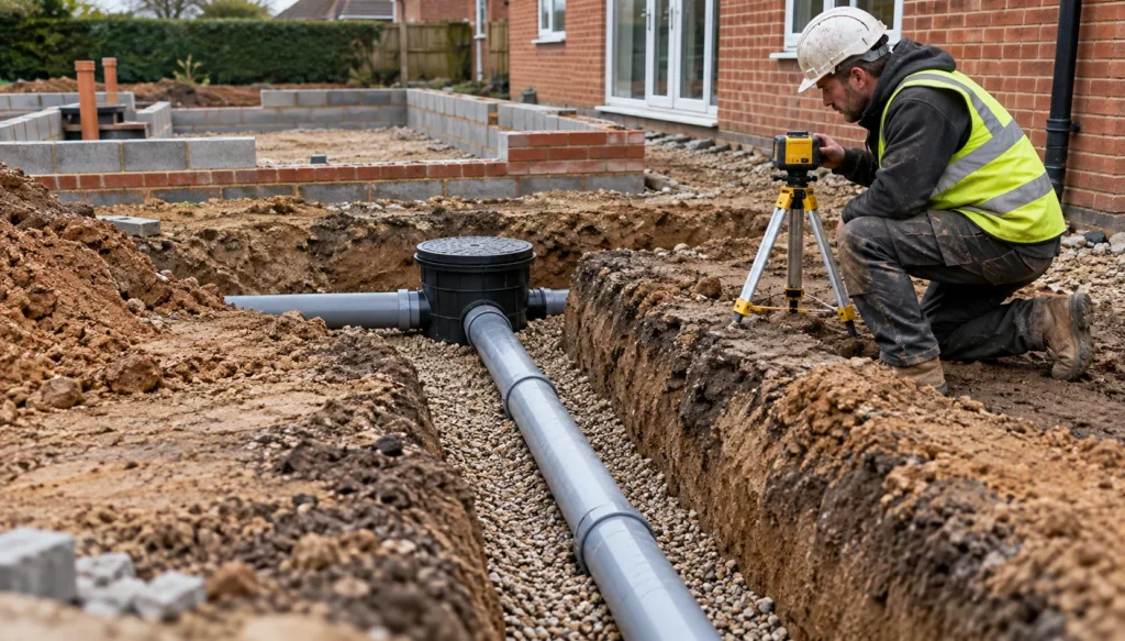
Lay a pipe too flat and solids settle along the invert. Recurring blockages follow. Lay it too steep and liquid outruns the solids, stranding paper and waste. Groundworkers set exact invert levels with optical or laser levels before bedding the pipe. The run must sit on granular material so the gradient holds over decades.
Ventilation and trap seal retention
Discharge stacks need ventilation to stop pressure swings siphoning fixture traps. A 110mm soil and vent pipe terminating above the eaves maintains equilibrium. Air admittance valves offer an approved alternative inside ventilated service ducts. From experience across the sector, poor stack ventilation is a common cause of recurring odour complaints in extensions.
Every sanitary appliance needs a trap with a specified seal depth. Sinks and basins typically carry a 75mm seal. Without it, sewer air migrates into living space. Designers must keep branch discharge pipes within the permitted lengths. Over-long branches create hydraulic draw. That draw empties fixture traps during heavy discharge.
Public sewer protection and water undertaker approvals
Public sewer proximity and statutory consent
Building within three metres of a public sewer triggers the need for a formal build-over agreement. Water undertakers hold statutory rights to maintain, inspect and repair public apparatus under the Water Industry Act 1991. Developers cannot start nearby excavation until the undertaker grants technical approval. That approval runs separately from building control.
The undertaker assesses whether foundation loads will transfer stress onto the sewer below. Sewers deeper than 1.5 metres attract closer scrutiny. So do pipes above 160mm in diameter. Undertakers refuse consent outright where a proposed envelope would encase a manhole. They also refuse where the scheme removes plant access to the run.
Engineering details for sewer crossings
Contractors crossing a public sewer must isolate the pipe from all vertical building loads. Where trench-fill foundations pass over an active drain, the contractor installs reinforced concrete lintels across the trench. Compressible packing around the barrel absorbs deflection. This detail stops structural movement cracking the conduit during and after construction.
Building control surveyors inspect these bridging details before any concrete is poured. Where foundations sit alongside a sewer run, the foundation base must reach the sewer invert depth or lower. That alignment removes lateral surcharge against the pipe wall. CCTV surveys before and after the works confirm the sewer remains intact.
Did You Know?
The Water Industry (Schemes for Adoption of Private Sewers) Regulations 2011 transferred private shared drains and lateral connections to water undertakers on 1 October 2011. Many domestic extensions now sit over adopted public sewers. Owners often discover this only once building control asks for a build-over agreement.
Surface water drainage and the statutory hierarchy
Discharge hierarchy application under Requirement H3
Requirement H3 obliges designers to discharge surface water by the most sustainable method available. The hierarchy places ground infiltration through soakaways first. Discharge to an adjacent watercourse ranks second. A connection to a public surface water sewer sits last. Building control treats that final option as a genuine last resort.
Developers must show why the higher options fail before a sewer connection gains approval. Infiltration testing to BRE Digest 365 establishes the percolation rate. It also confirms whether infiltration is viable at all. Dense cohesive clay frequently fails those tests. Designers then fall back on an attenuated discharge to the public storm network.
Soakaway design and boundary clearances
A domestic soakaway must sit at least five metres from any building foundation. That clearance stops saturation destabilising the supporting ground. Approved Document H also requires clear distances from public highways and neighbouring boundaries. Sizing depends on the impermeable roof area served and the local rainfall return period used in the calculation.
Engineers calculate storage volume using geocellular crates wrapped in permeable geotextile. The membrane keeps fine silt out of the void space. Without it, storage capacity drops steadily over time. The soakaway invert should stay at least one metre above the seasonal high groundwater table. Reliable dissipation depends on that margin.
Ground conditions and structural foundation interactions
Cohesive clay movement and moisture changes
Cohesive clay expands and shrinks as groundwater levels and root moisture extraction change. Concentrating surface runoff into clay near domestic footings softens the subgrade. Bearing capacity then drops. In practice, we find this is the usual driver of differential settlement at the junction between an extension and the original structure.
Engineers working in clay commonly specify deeper trench-fill footings. Piled ground beams offer an alternative where stable strata sit further down. Drainage pipes passing through external walls need flexible joints close to the masonry face. Those articulated joints absorb minor movement. They stop rigid pipework shearing or solvent-weld collars snapping.
Bedding materials and trench excavation stability
Drainage trenches need careful excavation, stable benching and proper granular bedding. Approved Document H calls for clean, non-cohesive aggregate beneath below-ground pipes. Ten millimetre single-sized pea gravel is the usual choice. Contractors must never bed foul or surface water pipework directly onto loose backfilled soil, whatever the programme pressure.
Granular bedding cushions the pipe barrel against point loading from stones in native backfill. Side-fill is compacted by hand to 100mm above the pipe crown. Mechanical compaction follows only after that. In waterlogged or unstable ground, trench support protects operatives. It also stops side collapse disturbing nearby existing foundations.
Inspection access and maintenance infrastructure
Inspection chamber spacing and dimensional rules
Approved Document H requires an access point at every change of direction, gradient or pipe diameter. On straight runs, inspection chambers must sit no more than 45 metres apart. That spacing allows mechanical rodding and jetting from ground level. Chamber dimensions must then match the invert depth at each position.
For invert depths up to 0.6 metres, a 190mm minimum internal size is acceptable. Between 0.6 and 1.2 metres, that minimum rises to 450mm. Chambers deeper than 1.2 metres keep the 450mm internal size. Their surface opening must be restricted to 350mm circular or 300mm square to prevent personnel entry.
Roddable access points and terminal fittings
Sealed access fittings on internal stacks let operatives clear blockages without stripping out sanitary fixtures. These rodding eyes need bolted or threaded cover plates with durable elastomeric gaskets. Position them above the flood level of the connected appliances. That placement prevents internal spillage whilst a blockage is being cleared under pressure.
Outside, long branches terminating at a gulley need a roddable access point within the gulley body. Contractors fit dry-access rodding eyes at the head of each drain run. That gives uninterrupted access toward the sewer. Swept junctions rather than sharp elbows let cleaning equipment pass without jamming in the bend.
What We Build

House extensions
Single, double-storey and wraparound extensions — load-bearing structure engineered, materials matched to existing fabric, full Building Regulations compliance.

Home renovation
Whole-house renovation before you move in. Structural reconfiguration, open-plan steelwork, drainage, energy upgrades and fit-out under one point of accountability.

Bespoke new builds
Architect-designed one-off homes and replacement dwellings. JNR acts as Principal Contractor under CDM 2015 — groundworks to Completion Certificate.

Loft conversions
Dormer, hip-to-gable and full-mansard conversions — head-height assessment, Part B fire safety, Part K staircases and engineered structural roof alterations.

Commercial construction
Refurbishment and fit-out for offices, professional practices, retail and hospitality — CDM 2015 governance, Part B fire design, phased around live trading.

Heritage Renovation
Conservation area and listed building work — lime mortar pointing, sash window reproduction, breathable repairs and Conservation Officer-approved details.
Separate versus combined drainage configurations
Hydraulic surcharge risk in combined networks
Many older urban centres still rely on combined sewers. These carry foul sewage and storm runoff in one conduit. Heavy rainfall surcharges the pipe. Contaminated water then backs up through basement fixtures and external gullies. Designers must fit anti-flooding valves or pumped loops to protect vulnerable below-ground installations from that risk.
Approved Document H discourages connecting new roof areas to combined networks. That option stands only where every sustainable alternative proves impossible. Extra surface input worsens storm overflow spills into river catchments. Where an undertaker does permit a combined connection, engineers must fit flow restrictors to cap discharge during storm peaks.
Dual systems and misconnection prevention
Modern developments run strictly segregated networks. Foul waste travels to municipal treatment works. Clean rainwater discharges to a watercourse or soakaway. Connecting a foul appliance to a surface water drain is an offence under environmental legislation. Water companies and the Environment Agency both pursue misconnections once they trace the source.
Plumbing contractors must trace every below-ground connection before trenches are capped. Building control inspectors use dye or smoke testing to confirm internal appliances discharge only to foul stacks. Colour-coded covers, pipe markings and segregated chambers help. They stop later trades creating accidental misconnections during refurbishment or fit-out work.
Non-mains drainage systems and private treatment plants
Septic tank limitations and discharge restrictions
Septic tanks provide primary settlement only. They do not treat soluble wastewater to modern environmental standards. Current rules prohibit any septic tank discharging effluent directly into a ditch, stream or other surface watercourse. Effluent must pass into a designed drainage field, where aerobic soil layers deliver secondary biological treatment.
Approved Document H sets a minimum capacity of 2,700 litres for up to four users. Capacity increases for each additional user beyond that. The tank must sit at least seven metres from habitable parts of a building. It must also stay clear of vehicle routes unless the cover is reinforced.
Package treatment plant installation criteria
Package treatment plants use mechanical aeration to cultivate aerobic bacteria. That process breaks down organic waste to a far higher standard than settlement alone. Treated effluent can discharge directly to a watercourse, subject to Environment Agency general binding rules. These units are now the default for properties beyond public sewerage.
Installation needs an uninterrupted electrical supply for compressors, rotors and alarms. Maintenance engineers must reach the unit easily for annual sludge removal by tanker. The vessel sits on a concrete slab. That slab counteracts hydrostatic uplift, which can float an empty tank out of the ground in high water table conditions.
Final Thoughts
Compliance with Building Regulations Part H depends on early investigation, accurate levels and careful execution on site. Drainage is not an afterthought beneath the architectural layout. Establish sewer positions, ground permeability and invert levels at feasibility stage. That work removes unexpected regulatory halts and gives the finished structure stable support.
Undertakers and building control bodies continue to tighten enforcement around stormwater disposal and network capacity. Climate projections point to heavier, more frequent rainfall across the UK. Legacy below-ground assets will feel that strain. Designing self-cleansing foul runs alongside high-capacity sustainable surface drainage protects property against backflow, movement and environmental damage.
Let's discuss your vision.
You don’t need a full set of architectural drawings to speak to us. Whether you’re at the napkin-sketch stage or ready to build, we’re here to offer expert advice.
Frequently Asked Questions
Q: What is the minimum fall required for a 110mm foul drain?
A: Approved Document H sets a minimum fall of 1:80 for a 100mm nominal foul drain, sold as 110mm pipe, where it serves at least one WC. Where peak flow drops below one litre per second, the gradient must steepen to 1:40. Both figures aim at a self-cleansing velocity of 0.75 metres per second. Correct falls stop solids settling along the invert. They also stop liquid outrunning heavier waste.
Q: When is a build-over agreement required for a house extension?
A: A build-over agreement with the sewerage undertaker is required whenever proposed works, foundations or footings sit within three metres of an adopted public sewer. The rule applies equally to shared laterals that passed into public ownership under the private sewer transfer regulations in 2011. Water companies assess foundation loading and maintenance access before granting consent. Starting excavation without that consent risks enforcement and the cost of remedial works.
Q: Can I discharge surface water into a foul sewer under Part H?
A: No. Building Regulations Part H prohibits discharging clean rainwater into a foul sewer. Designers must follow the discharge hierarchy and direct runoff to a soakaway or watercourse wherever practicable. Only where no separate storm network exists and infiltration testing fails will an undertaker consider an attenuated connection to a combined public sewer. That consent depends on the network having spare hydraulic capacity at the connection point.
Q: How far from a building must a soakaway be constructed?
A: A rainwater soakaway must sit at least five metres from the external foundations of any building. That clearance prevents concentrated infiltration washing out sub-base fines or saturating cohesive clay beneath strip foundations. The soakaway should also sit clear of neighbouring boundaries and public highways. Positioning it too close risks waterlogging adjacent land or softening a roadway sub-base during severe storms, which can trigger a civil claim.
Q: What is the maximum distance permitted between inspection chambers?
A: Approved Document H permits a maximum of 45 metres between inspection chambers on a straight run. Access points are also required at every change of direction, every change of gradient and every change of pipe size. Head-of-drain positions need access too. This spread of access covers lets operatives clear stubborn blockages and deploy jetting equipment from ground level without excavating the pipe run.
About The Author
Julian Rowlands is the founder and director of JNR Construction Limited, a Cheshire-based Master Builder and Design-to-Build contractor established in 2006. A Federation of Master Builders member and TrustMark-registered contractor, Julian has spent over two decades delivering complex residential and commercial projects across Cheshire and southern Greater Manchester — from heritage refurbishments and structural extensions to bespoke new builds and architect-led commercial schemes. He writes on the regulatory, technical, and project management realities of UK construction, with a particular focus on CDM 2015 compliance, Building Regulations, and the practical detail of bringing architectural design into built form.


